
When it comes to understanding the components of a wiring diagram for a garage door sensor, it’s essential to have a clear understanding of the various parts involved. As an expert in the field, I’ll guide you through the key elements that make up this crucial system. From the sensor itself to the power supply and the connection points, each component plays a vital role in ensuring the smooth operation of your garage door. So, let’s dive in and explore the essential components that make up a wiring diagram for a garage door sensor.
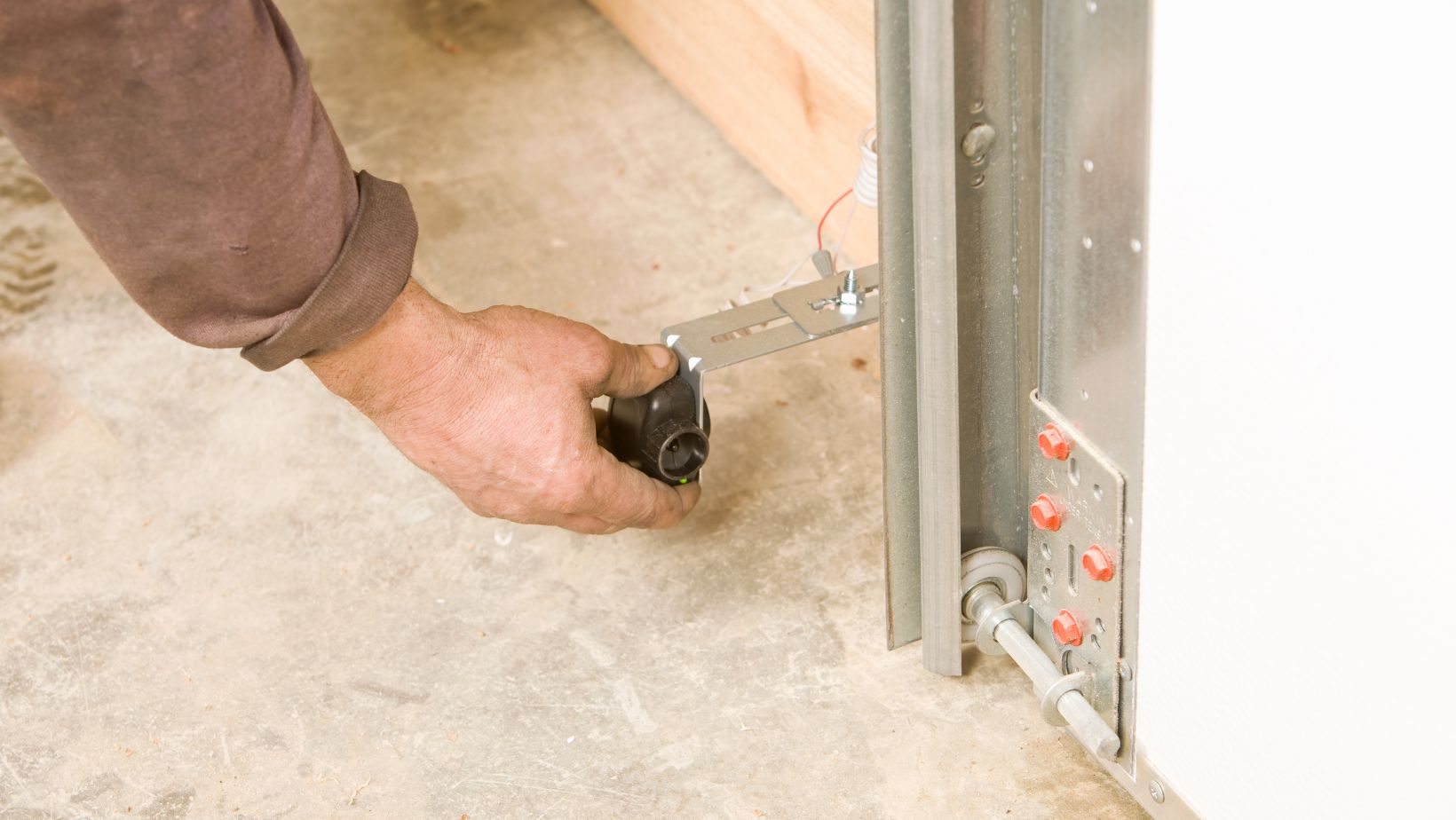
One of the primary components of a garage door sensor wiring diagram is the sensor itself. This small but mighty device is responsible for detecting any obstructions in the path of the garage door. By sending signals to the control unit, the sensor ensures that the door stops or reverses its movement if an object is detected. It’s crucial to understand the wiring connections for the sensor to ensure its proper functioning and overall safety.
Wiring Diagram For Garage Door Sensors
The garage door sensor is a crucial component of the overall garage door system. It plays a vital role in ensuring the safety and smooth operation of the door. In this section, I’ll take you through the key aspects of understanding garage door sensors.
1. Function of a Garage Door Sensor
The primary function of a garage door sensor is to detect obstructions in the path of the door. This ensures that the door does not accidentally close on objects or people, preventing potential accidents or damage. The sensor detects any obstruction and sends a signal to the control unit, which then stops or reverses the door’s movement.
2. Power Supply for the Sensor
To operate effectively, the garage door sensor requires a power supply. This can be either a low-voltage electrical connection or batteries. It’s important to ensure that the sensor is adequately powered for it to function properly. Regular maintenance checks and battery replacements, if applicable, are essential to keep the sensor working at its best.
3. Connection Points in the Wiring Diagram
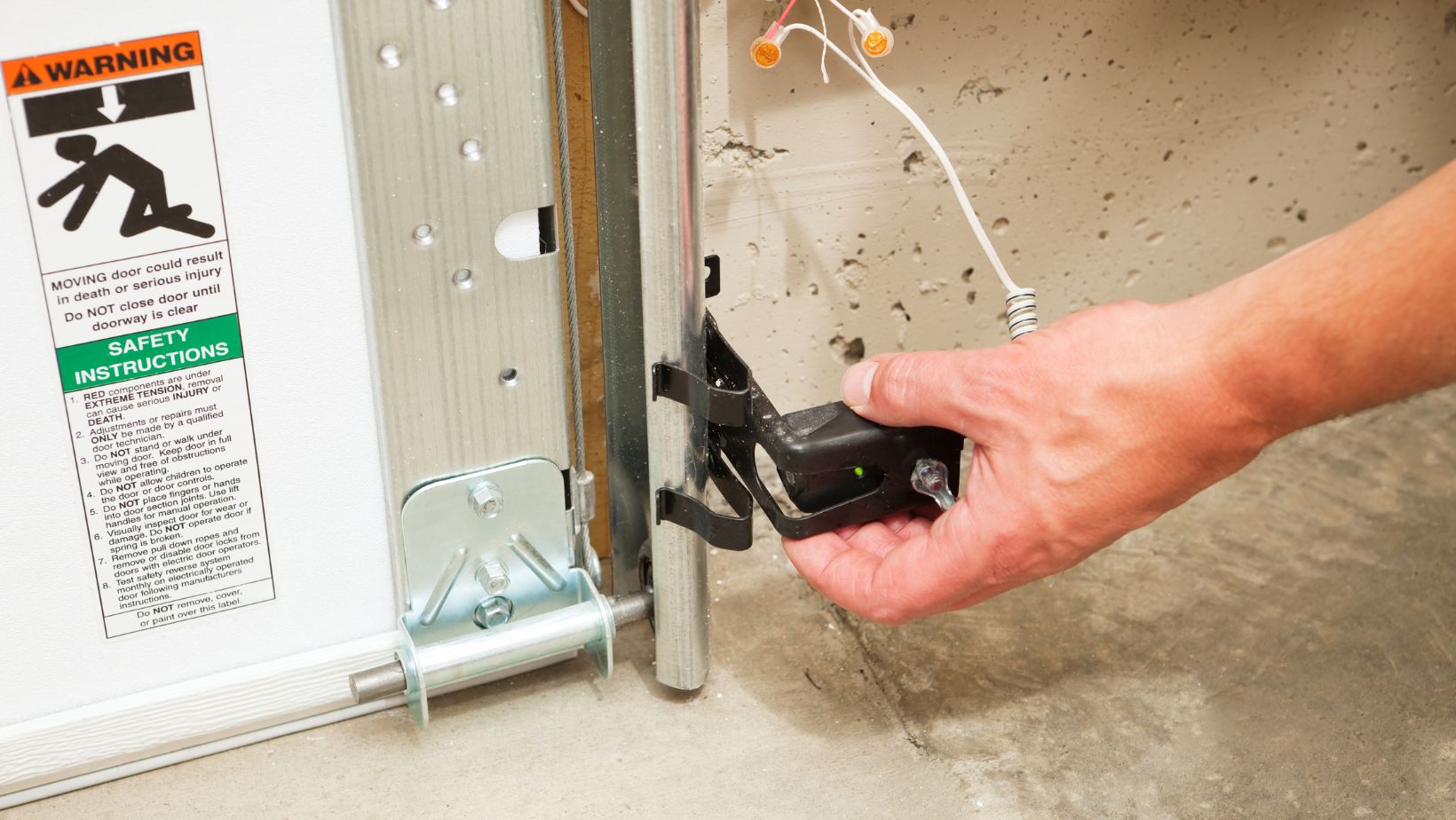
The wiring diagram for a garage door sensor includes several connection points that establish communication between the sensor, control unit, and garage door opener. These connection points enable the sensor to send signals to the control unit and execute the appropriate action, ensuring the door’s safe operation. It’s crucial to understand how these connection points are properly wired to ensure the sensor functions as intended.
Power Source for Garage Door Sensors
One of the key components of a wiring diagram for a garage door sensor is the power source. The power source is responsible for supplying the necessary electrical energy to the sensor, allowing it to function properly. There are two main options for powering garage door sensors: a low-voltage electrical connection or batteries.
Low-Voltage Electrical Connection
Many garage door sensors are designed to be connected to a low-voltage power source. This type of connection requires a transformer to step down the voltage from the main electrical supply to a lower, safer level for the sensor to operate. The low-voltage connection is often more convenient and cost-effective, as it eliminates the need for frequent battery replacements.
To establish a low-voltage connection for your garage door sensors, you will need to locate the power supply transformer and connect it to the sensor according to the wiring diagram. It is crucial to follow the manufacturer’s instructions and guidelines to ensure proper installation and avoid any electrical hazards.
Battery Power
On the other hand, some garage door sensors are designed to be battery-powered. This option is ideal for situations where a low-voltage power source is not readily available or where the convenience of battery-powered sensors outweighs the need for a wired connection.
To power a garage door sensor using batteries, you will need to insert the required batteries into the sensor according to the manufacturer’s instructions. It is important to regularly check the battery status and replace them as needed to ensure uninterrupted sensor functionality.
Conclusion
Understanding the components of a wiring diagram for garage door sensors is crucial for a successful installation. By following the manufacturer’s instructions and guidelines, homeowners can ensure the smooth and safe operation of their garage door system.
The key components discussed in this article include the sensor, emitter, receiver, control unit, and power source options. It is important to note that battery-powered sensors require regular battery checks and replacements to maintain optimal functionality.